Assignment #1: Image Matting & Compositing
Date handed out: 11/01/2014; Due date: 27/01/2014
PDF version
Overview
In this assignment you will implement and experiment with an interactive image matting tool. This tool was demonstrated in class in Lecture 1 and will be discussed in detail next week. Apart from implementing a specific matting technique called Triangulation Matting, the interface you will work with will also serve as an image manipulation front-end for future assignments. In fact, each assignment will add more functionalities to this front end.
Right now, the goal of this assignment is two-fold:
- To be come familiar with
- the FLTK user interface design library and the FLUID user interface builder software
- using the CDF Linux machines to write user interface code
- using the VXL image processing library to read/write images, display them on the screen through the user interface and access their pixel information
- solving linear systems using some basic numerical routines in VXL
- To implement your very first image analysis technique and get some cool results!
While the due date for the assignment is 2 weeks away, it is strongly advised that you try and complete Part A.1 of the assignment within the next few days and use the rest of your time for Part A.2 and Part B. It will take some time to familiarize yourself with the FLTK programming model, the VXL library, and the helper code that I have already written, so start early!!! Once you "get the hang of it," the programming part of the assignment should not be that hard and there is very little coding for you to do. But it will take you quite some time to internalize exactly what you have to do, and how.
NEW: At the bottom of this page you will find information about how to work on your assignment in VisualC++.Triangulation Matting
The technique we will implement is based on a paper by Smith and Blinn that appeared in SIGGRAPH'96. You do not need to read or look at this paper (it's not particularly well written...).
We are providing you with a full-blown implementation of the tool in executable form, along with a suite of test images, so that you can run it yourself and see how it works (see the executables partA-2/bin/VisComp_full.exe and partA-2/bin/viscomp_full in the assignment tarfile). The program should work for a variety of image formats (tif, jpeg, etc). I suggest you use very small images to test things out first. In fact, the full-blown executable will only accept images whose largest dimension is less than 512 pixels. When you write your own version, you can change the size of the maximum displayable image in the supplied source code (there is documentation about that in the code). Also, if you are running the tool on CDF but working remotely from a home machine, the tool will not run if your X server does not support the GLX extension.
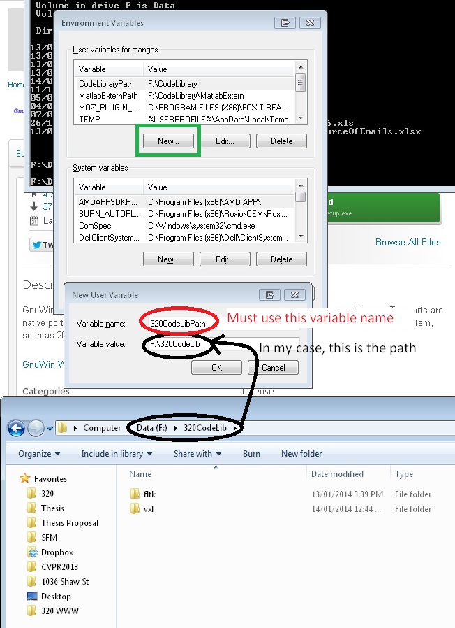
Briefly, the tool works by first loading pictures of an object in front of two different backgrounds (they can be found in the partA-2/test_images sub-directories):
You can think of these photos, called Composite 1 and Composite 2, as being the superposition of two different background images with a single "foreground" image of the object.
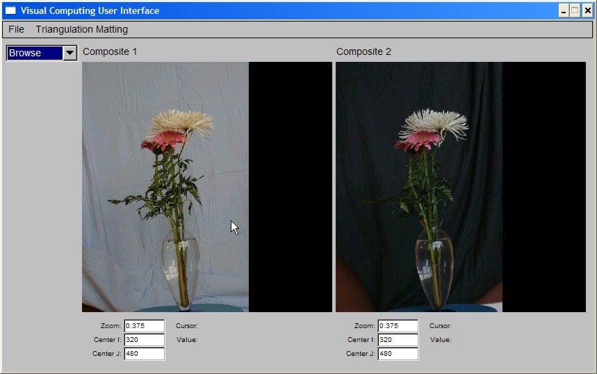
Next, we load two more photos, called Background 1 and Background 2, that show only the backgrounds:
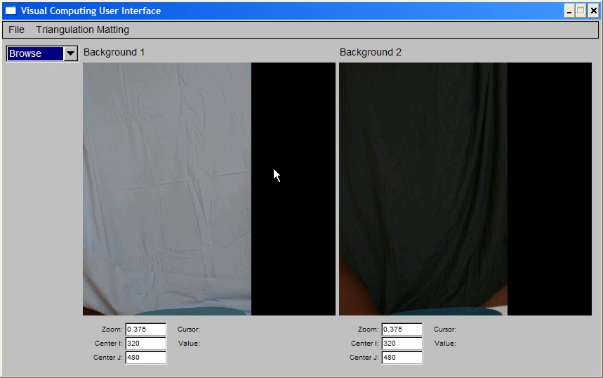
From this set of four photos, the matting algorithm computes two images: an Alpha Matte, that tells us which pixels in Composite 1 and Composite 2 correspond to the foreground object and also estimate the "transparency" of those pixels and an Object photo, that is a photo of the foreground object only (ie. all background information has been removed):
The Alpha Matte is a grayscale image, where the grayscale value indicates transparency (0 is fully transparent, 1 is fully opaque). For example, the pixels of the glass vase have small grayscale values, indicating that the vase is semi-transparent, while the flowers have alpha close to 1, indicating that the flower petals are not transparent at all. You can zoom in to get a better sense of the alpha values for different parts of the image by changing the zoom settings in the UI.
Once the Alpha Matte and Object photos are computed, you can create new image composites through superposition of the Object photo with a new background photo, according to the computed Alpha Matte:
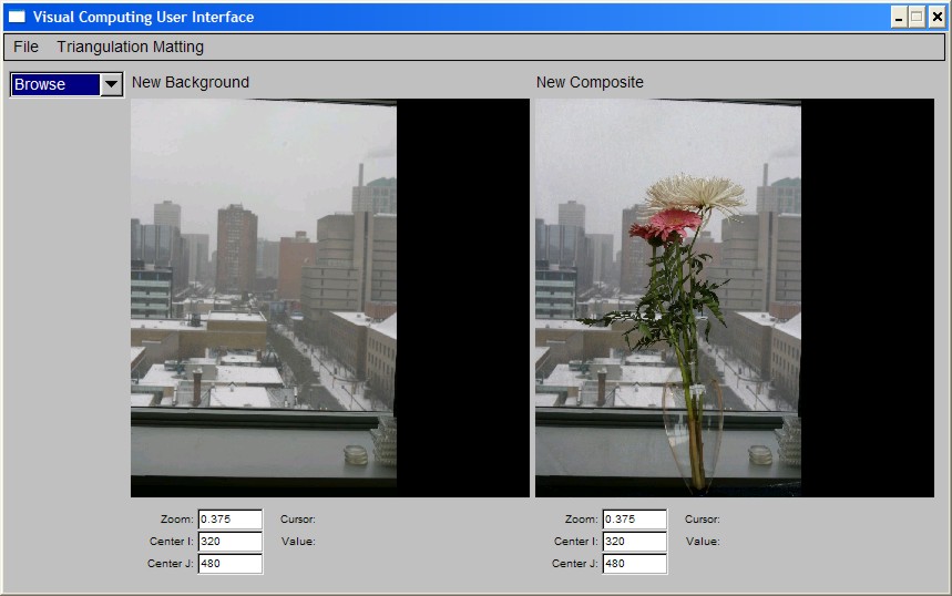
Note how the background image appears to "show through" the vase.
Interactive vs. Non-Interactive (batch) Operation
The supplied program can be run in interactive mode (ie. UI windows are displayed and user works through menus and/or keyboard accelerators), in batch mode (ie. user supplies a set of command-line options specifying the input and output images names) or both (ie. some or all command-line options are specified and, after images are loaded, the UI windows are displayed as well). Type 'viscomp -help' to see the command line options.
Your Tasks
For this assignment you will have to do the following:
- Familiarize yourself with the FLTK tooklit (see Part A.1 of the assignment below)
- Familiarize yourself with the triangulation matting algorithm (to be discussed in class next week)
- Run your own triangulation matting experiments, by taking pictures with your digital camera (at home, outside, or anywhere else you'd like) and applying the matting algorithm to them (see Part B.1 of the assignment below)
- Implement the triangulation matting algorithm and integrate it into the supplied "starter code" (see Part A.2 of the assignment)
- Answer a set of written questions about the triangulation matting process (see Part B.2 of the assignment)
- Extend the "crippled" interface in the starter code to match the functionality of the full-blown implementation (see Part A.3 of the assignment)
I suggest you use the above order in tackling these tasks. Specifically:
- You should start getting familiar with FLTK as soon as possible; this part of the assignment is very easy, and does not depend on the matting procedure in any way.
- You can use the supplied "solution" executables for doing your experiments; you do not have to wait for your own implementation to be ready. See the top of file 320/Matting/partA-2/README.1st for a brief description of how to run it (also available here).
- You will not be able to answer some of the written questions without having first implemented the algorithm, and without having run your own experiments. I suggest you leave some of these questions for the end of the assignment.
- You can test your matting implementation by running it in batch mode first. This way you don't have to worry about the interactive component of the interface.
- The additions to the UI you need to do are straightforward and fairly minimal, and they do not depend on your matting implementation per se. You can tackle these at any time.
Part A: Programming Component (70 Points)
Part A.0: Unpack the Helper Code
The updated helper code is packaged into the tarfile matting.tar.gz. If you got a copy of the started code prior to Monday Jan 13 at 10pm, the binary viscomp_full will not run, and partA-2 will not compile. Please download this new version. The following sequence of commands creates a directory called CS320 in your home directory on CDF and unpacks the code:
> cd ~
> tar xvfz matting.tar.gz
> rm matting.tar.gz
This will create the directory ~/CS320 along with files and subdirectories needed for the assignment. All the code that you turn in should be in those directories as well, exactly as specified in the details below.
Part A.1: Getting familiar with FLTK and FLUID (10 points)
This part of the assignment will help you get familiar with the FLTK toolkit and FLUID, a program for interactively creating user interfaces.
- Dot file initialization
In order to use any of the toolkits required for the course, you need to set up your Unix environment. To do this, you will need to modify your .cshrc file so that it correctly defines certain environment variables. A sample file can be found in directory 320/Matting/partA-1. You can take a look at it and then use it modify your .cshrc file, located in your home directory, accordingly.
After you have modified your .cshrc file, execute the following commands at the shell to make the new settings take effect:
> source .cshrc
> rehashTo test whether your paths are now set correctly, try running the command
> fluid
You should now see the main window of fluid on your screen. If you get an error instead (e.g., "command not found"), your paths are still not set up correctly. In this case, it is strongly advised that you replace your own .cshrc file with the sample file and try again. If things still don't work, make sure you are working on a CDF machine running Linux.
- The FLTK and FLUID documentation
One of your tasks in this assignment is to get as familiar as possible with FLTK and FLUID. Fortunately, there is a wealth of on-line documentation about these tools. The starting point for the documentation is here.
Note that there is A LOT of documentation here, so it is important to take it easy and be selective about what you read. As you become more and more familiar with these tools throughout the course, you can venture into some of the more advanced topics covered in the manual.
The first thing to read are Chapters 1 and 2 of the FLTK documentation. In Chapter 1, ignore all sections about "Building and Installing FLTK Under ...". All software has already been installed so you don't have to worry about all this.
You should become thoroughly familiar with the "First FLTK Program" discussed in Chapter 2. It is strongly advised that you copy the program into the directory 320/Matting/partA-1 (call the program hello.cxx), compile it, and run it.
To do the compilation, you can use the Makefile located in that directory simply type
> make hello
This should run the compiler with all the necessary flags and create an executable that you can run from your shell. While you are not required to turn in anything related to this program, it is highly unlikely that you will be able to complete the rest of the assignment if you cannot get through this stage. (Note: if you want to see what the command 'make hello' really does, type 'make -n hello' and this will display the sequence of compilation steps that are executed.)
UPDATE: The supplied makefile in the directory /CS320/Matting/partA-1/ is designed for the CubeView program. To compile hello using the same makefile you must add the following section:
hello: hello.o
$(CC) -o hello hello.o $(LDFLAGS)
which is quite similar to the linker section of CubeView (see file for details). The key is to place the libraries after the executable and the object file names (common practice, details here).
- Building a sample interactive application with FLUID
Now that you've completed Chapter 2 and ran the sample program, you are ready to dive into fluid, which is the main tool we will be using to create user interfaces. You will learn the basics of fluid by creating, step-by-step, a simple interactive application that is described in detail in Chapter 9 of the FLTK manual.
At this point, you should skip Chapters 3-8 of the FLTK manual and go straight to Chapter 9. The chapter contains a brief tutorial that guides you step-by-step through the construction of a simple graphical viewer called CubeView.
The main task in Part A.1 of the assignment will be to create a fully-functional version of the CubeView program. To help you with this process, we are providing a partially-completed version of the program that you will have to finish up yourselves, guided by the tutorial in Chapter 9.
Step 1: Notice the files CubeView.h, CubeView.cxx , CubeMain.cxx and Makefile in the "partI" subdirectory. These files provide the partial code you will need to get a complete implementation of CubeView running. Compile them by typing
> 320/Matting/partA-1
> makeand make sure that the only errors generated are because of the CubeViewUI.cxx file that you haven't created yet.
Step 2: Run 'fluid' from the 320/Matting/partA-1 directory and go through all steps in the Chapter 9 tutorial (you can skip the section called "The CubeView Class" for now). Note that all the code under the heading "The CubeView Class" is included in the helper files you downloaded so you don't need to type it in yourself. Basically, your main task will be to run fluid and use it to create the CubeViewUI class and associated files, as described in the chapter. Once you are done following all the instructions in the tutorial, be sure to save your work by selecting File->Save As, naming the output file CubeViewUI.fl, and saving this file in the partA-1 directory. Naming is important so be sure to save the file with this exact name. To generate the code implementing the CubeViewUI class, select the File->Write Code menu option in fluid. Again, make sure that all the files you create go in the partA-1 directory.
Once fluid has generated the code implementing the class, you need to compile it by running 'make CubeViewUI.o' and making sure that it compiles correctly.
Step 3: You are now ready to create an executable version of the program. To do this you need to link together the CubeMain.o CubeViewUI.o and CubeView.o object files to create an executable called CubeView. The supplied Makefile should do this for you by running 'make' again. You are done!
- What we will be looking for in the 320/Matting/partA-1 directory:
- The CubeView executable
- That the CubeView executable and related object files can be compiled/created by just typing 'make' at the Unix prompt while in that directory
- The file CubeViewUI.fl that you created with fluid
Part A.2: Implementing the Triangulation Matting Algorithm (50 points)
The goal of this part of the assignment is to implement the triangulation matting algorithm to be discussed in class. The algorithm takes four RGB images as input (Composite 1, Background 1, Composite 2, Background 2) and produces two images as output---a grayscale Alpha Matte, and an RGB Object image.
- Your starting point: The file 320/Matting/partA-2/README.1st gives a fairly complete description of the starter code.
- There are a lot of different components to the already-provided code, which is a lot to wade though, so you need to concentrate on the parts directly relevent to the assignment. Three files are the most important, which implement the matting class. These files are under the src/matting subdirectory:
- First look at src/matting/matting.h. This file is where the class methods are defined, which provide the interface between the interactive UI and the matting algorithm. All methods are fully implemented except for the compute() method and the compute_composite() method.
- Then look at the process_args() function in file src/main.cxx. This shows how these methods are used when running the program in batch mode.
- Your goal is to implement those two methods. A portion of the code is already in src/matting/matting_algorithm.cxx. Your task for this part of the assignment is to complete that code.
- The file matting.cxx contains the class constructor and various utility functions which you may need.
- (40 points) The behavior of the compute() method should be as follows:
- If the four input images (held in the class members back_1_, back_2_, comp_1_, comp_2_ ) have already been specified, the method computes the alpha matte and the object image and places them in the members alpha_ and object_, respectively.
- The method returns true if the computations were performed correctly and false if there was a problem (eg., not all 4 required input images are available)
- You can select "Triangulation Matting->Run Algorithm" from the menu of the solution executable to see what the result of this computation should be.
- (10 points) The behavior of the compute_composite() method should be as follows:
- If the alpha and object images have already been computed (held in class members alpha_ and object_) , the method should combine a new background image (supplied in the parameter new_background) with the already-computed object_ image, and place the result in the parameter new_composite.
- The method returns true if the computations were performed correctly and false if there was a problem (eg., the alpha and object images have not been computed yet)
- You can select "Triangulation Matting->Create Composite" from the menu of the solution executable to see what the result of this computation should be.
- If the compute() method is implemented correctly, you should be able to run the algorithm and save its results using the command-line invocation:
viscomp -no_gui -mback1 <back1> -mback2 <back2> -mcomp1 <comp1> -mcomp2 <comp2> -mobj <obj> -malpha <alpha>
this will save the results in two images, <alpha> and <obj>.
- If the compute_composite() method is also implemented correctly, you should be able to get the results of this function as well by adding two more command-line options to the above command line:
-mnewback <newback> -mnewcomp <newcomp>
- If your implementation uses additional files (eg. for callbacks, or if you split your implementation over multiple files under the matting/ directory) make a list of these files in the file src/ADDITIONS, along with a 1-2 sentense explanation of what is in them.
Part A.3: Completing the User Interface (10 points)
The last step in PartA of your assignment is to extend the "incomplete" user interface of your starter implementation so that it matches the functionality of the full version. The starter implementation has the following components missing (you can run both versions to verify what needs to be implemented):
- (5 points) The "Triangulation Matting->Save" menu. You need to create the menu and implement callbacks that save the algorithm's results.
- (5 points) The right drop-down menu in the "Matting Display Control" window. You need to add the drop-down menu and add the callbacks needed to get the behavior exhibited by the full version.
Both of these functionalities should be implemented through fluid by running fluid on the file 320/Matting/partA-2/src/VisCompUI.fl. As stated in the README.1st file, any callbacks you implement must be placed in the student_callbacks directory.
Part B: Non-Programming Component (30 points)
This part of the assignment is meant to assess your detailed understanding of the matting algorithm and to have you perform some matting experiments of your own!!
Part B.1: Conduct your own Triangulation Matting experiment (10 points)
Use your own digital camera to capture a set of images suitable for the triangulation matting procedure, and run the algorithm on those images.
Specifically, you need to
- capture 5 JPEG images with your camera (Background 1, Background 2, Composite 1, Composite 2, New Background)
- use them as input to the matting program (either your implementation or the fully-functional executable we supplied) to create 3 output images (Alpha Matte, Object, New Composite)
- place all 8 images in the directory 320/Matting/partB
CAUTION: you should name these images back1.jpg, back2.jpg, comp1.jpg, comp2.jpg, alpha.jpg, object.jpg, newback.jpg, newcomp.jpg. - answer the questions in file 320/Matting/partB/Written.txt (also available here) about how these images were taken
Note that the question of how you acquire your 5 input images will require some thinking/planning on your part!! The number of points you get for this part of the assignment will be based on how good your matting results are or, if they aren't, on your assessment of why it was not possible to get better results.
If you do not have a digital camera and cannot borrow one from a friend, let me or the TAs know RIGHT AWAY and we will try to make suitable arrangements.
Part B.2: "Debugging" the Triangulation Matting process (20 points + 10 extra-credit points)
The triangulation matting algorithm does not always behave as one would expect from a quick glance of the photos at the beginning of this assignment! Here you need to answer a set of questions that examine what can go wrong and, more importantly, why.
You can find the questions in the file 320/Matting/partB/Written.txt (also available here). Write all your answers in that file.
Part C: Packing Everything Up and Turning It In
Once you are done with the above, edit the file 320/CHECKLIST.txt (also available here) to specify which components of the assignment you have completed, along with notes about parts that you were not able to complete, if any.
Pack up your portion of the code with the following commands:
> cd ~/CS320
> tar cvfz assign1.tar.gz Matting/CHECKLIST.txt Matting/partA-1/* Matting/partB/{WRITTEN.txt,*.jpg} Matting/partA-2/bin/viscomp Matting/partA-2/src/{VisCompUI.fl,Makefile,ADDITIONS} Matting/partA-2/src/matting Matting/partA-2/src/student_callbacks
Finally, you should use CDF's assignment submission system to submit your assignment:
> submit -c csc320h -a Assign1 assign1.tar.gz
Note that the system has been configured (1) to accept only files whose name is assign1.tar.gz and (2) to not accept submissions that are more than 4 days late. Just do 'man submit' at the unix prompt to get more info on this process.
In evaluating your assignment, the first thing we will look for are the files CHECKLIST.txt and WRITTEN.txt.
Then we will make sure that your code compiles (just by typing "make" in the partA-1/ and partA-2/src directories).
Then we will run your code on test examples in both the interactive and the non-interactive modes.
Finally, we will look at your code. It must be well commented: if the TA has doubts about the correctness of a specific implementational feature and there is not enough documentation/comments for the TA to decide, you will lose points.
Notes on VXL
In this course, we will be using the VXL library for representing and manipulating images. This is a library developed by dozens of computer vision researchers over many years, so it has very broad coverage in terms of functionality. As a consequence, the documentation is quite extensive. The best place to start is to look at Sam Hasinoff's old 320 page (from a previous instance of the course). There you will find introductory notes on VXL, pointers to the top-level documentation tree, as well as pointers to the two VXL modules that are directly relevant to you for this assignment: the vil library for representing images and the vnl library for numerical computations. Your TA will cover the basic structure and organization of VXL, and go over simple image manipulation functions. Another good source of information is, of course, the starter code!
- VXL has several modules
- VCL, a C++ compatibility library that provides standard classes such as strings, vectors, and I/O in a completely platform-independent manner.
- VNL, a numerical algorithms library
- VBL, a basic templates library
- VIL, the image library we will be using during the course
- VGL, a geometry library for defining and manipulating geometric objects such as vectors, curves, and surfaces
- VUL, a utility library which provides functions such as command line parsing.
- For now, you should become familiar with the VIL component of VXL, pay special attention to the vil_image_view class, which you will use to store and manipulate images. You should also look at the loading and saving functions (from the starter code), and get a general idea of what kind of functions for manipulating images are available.
- It is sometimes difficult to find documentation for a specific function starting from the top-level of the documentation hierarchy. I have found that google is perhaps the fastest way to get to the documentation of a specific VXL function!
Using Visual C++ Under MS Windows (Win2k, WinXP, Vista, Windows 7)
If you want to work in windows, and you got a copy of the starter code prior to this announcement, you must re-download the starter code. The new one has updated options that work with the new libraries.
However, your implementation MUST run on the Linux CDF machines and can only be submitted for linux.
Both fltk and VXL have been ported to windows, making the choice of operating system completely transparent: the code I am providing compiles without any changes on both Linux and Windows 7 (using VisualC++ 8). You should, in principle, be able to work in Visual C++, copy your code to your CS320 directory on CDF, compile using the supplied linux makefile, and run. Give yourself some extra time if you choose to do this. Ssometimes, bugs that do not seem to affect a program in VC++ cause coredumps on linux (and vice-versa).
If you plan to work with VC++ download the file 320CodeLib.zip (1.8GB !!!, almost 10 GB uncompressed!!). It contains the entire compiled VXL and FLTK distributions for 64-bit machines. This should work on your Windows computer with VC++ 8.0 (2005) installed, but I will not offer any support if you encounter problems with it. Alternative you may download sources for both VXL and fltk and compile them yourself. This distribution contains the latest libraries but older ones have worked. Once you decompress this library, add a system variable called 320CodeLibPath that points to the root of the decompressed files (instructions below) and the Visual Studio project should compile without issues. The provided code may work with more recent releases of Visual C++/Visual Studio and with Windows 8 but there are no warantees on that end either.
To create a user system variable hit the "windows" key and type the word 'path' (without the quotes). This will open the Environment Variables window. Then press new (green box in the image below) and enter the name '320CodeLibPath' (without quotes) and the path where you decompressed the libraries.