
Representing the Backbone of Tendon-driven Continuum Robots using Euler Curves
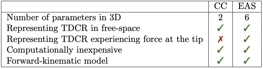
In one of the earlier posts, we learnt about the constant curvature (CC) representation. The approach assumes that the entire backbone can be represented as a circular arc, requiring two parameters in 3D space. From the Euler-Bernoulli theorem we know that the curvature of the beam is directly proportional to the moment experienced by it. Therefore, the CC representation can only model a constant planar moment experienced by the robot.
Due to its simplistic formulation, the CC is one of the most common backbone approximations made in literature. It has been shown that if there is no external gravitational, frictional, applied forces on the backbone, the tendon forces can be approximated by a constant moment applied on the segment 1. Since it requires only two parameters to represent the robot and uses geometrical assumptions, many closed form analytical models have been proposed that are computationally inexpensive as the formulation can be expressed as matrix operations.
However, if the robot is carrying a tool or camera at its tip for inspection and other tasks, there is bound to be a variation in curvature as shown below, and results in deviation from the CC shape.
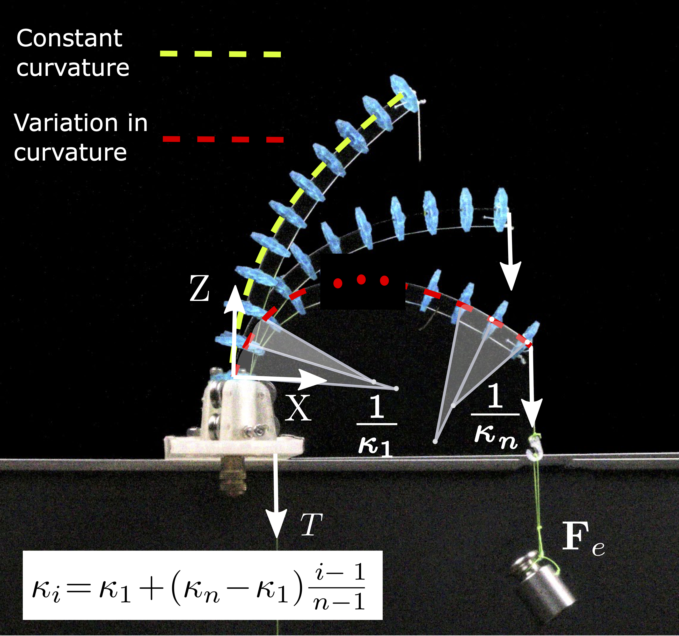 |
| Shape of a TDCR under different tip forces. The backbone can be approximated by the Euler Arc Spline representation as a series of \(n\) arcs with curvatures in arithmetic progression. When no force is applied, the robot curvature is constant (green) and \(\kappa_1=\kappa_n\). As the force increases, so does the variation in curvature (red) |
At ICRA 2019, Euler curves were proposed to represent long, heavy continuum robots 2. These are curves that have a linearly varying curvatures. Since long heavy continuum robots bend under the influence of gravity, we hypothesized 3 4 that they can be used to represent the backbone experiencing an external force at the tip as well.
- Euler Curve
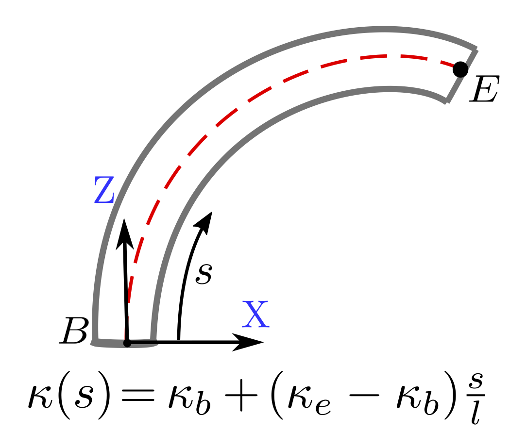
- The Euler curve (also known as the Euler spiral) is defined as a curve in which the curvature increases linearly with arclength.
History: The Euler spiral, defined by the linear relationship between curvature and arclength, was first proposed as a problem of elasticity by James Bernoulli, then solved accurately by Leonhard Euler. An Euler curve is known by several other names, including “clothoid,” and “Cornu spiral.” The underlying mathematical equation is most commonly known as the Fresnel integral. The profusion of names reflects the fact that the curve has been discovered several different times, each for a completely different application: first, as a particular problem in the theory of elastic springs; second, as a graphical computation technique for light diffraction patterns; and third, as a railway transition spiral. (Learn more about the mathematical history of the Euler spiral.)
Euler Arc Spline representation
When using Euler curves, the robot-independent mapping (configuration to task space) requires Fresnel integration which can add to the computation. In order to retain the advantage of the CC representation, where the configuration to task space mapping is computed by efficient matrix operations, we use the Euler Arc Spline (EAS) representation. This EAS representation of an Euler curve was first proposed by Meek and Walton 5 in the context of clothoids. To represent a continummum robot backbone with EAS, we use a series of arcs whose curvatures are linearly constrained and assumed to be in arithmetic progression as illustrated here:
 |
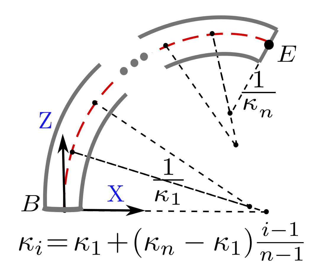 |
| CC representation | EAS representation |
The proposed representation can be extended to 3D by linearizing the components of curvature along all three axes, resulting in 6 parameters in total (two along each axes).
The EAS representation was tested on a set of 70 spatial TDCR deformations with two identical TDCR prototypes, operating both in free space and under the influence of an external tip force. It was found to represent the backbone shape with an average tip error of less than 0.5%. This result indicates that EAS is a powerful representation for continuum robots experiencing tip forces that cannot be achieved with CC represenations.
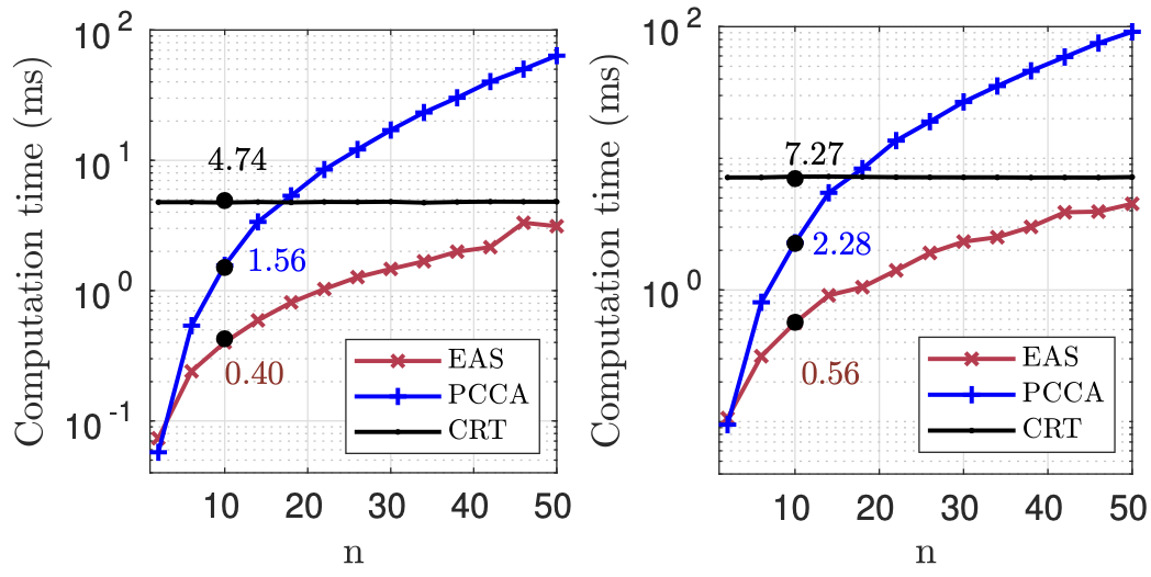 |
| Computation times of three models - EAS (red), CRT (black), and PCCA (blue) with increasing number of disks for planar (left) and non-planar (right) deformations. |
Potential
One of the major advantages of the backbone representation simplification is the reduced parameterization, without significant trade-off in accuracy. The lower number of unknowns offers the advantage of reduced computational time for a physics based model. Another advantage lies in its use in data-driven models. Lower number of configuration parameters requires lesser number of data points to train different models, allowing us to learn the behaviour of these robots due to unmodelled factors like manufacturing and assembly errors.
While we show the potential of Euler curves for TDCR experiencing tip forces, there are multiple avenues where its advantages could be exploited. It could be extended to model multiple forces along the backbone. Applying them for helical routing and learning their behaviour could be investigated to find the optimum routing to reach a particular target.
Further Reading: Curious to learn more about the use of Euler Arc Splines to model tendon-driven continuum robots? We published our finding in the IEEE Robotics & Automation Letters4 and presented our work at the IEEE International Conference on Intelligent Robots and Systems in 2022. For a quick summary, watch the video recording below! Paper Video
References
-
D. B. Camarillo, C. F. Milne, C. R. Carlson, M. R. Zinn, J. K. Salisbury: Mechanics modeling of tendon-driven continuum manipulators. IEEE Transactions on Robotics, 24(6):1262–1273, 2008. doi: 10.1109/TRO.2008.2002311 ↩
-
P. S. Gonthina, A. D. Kapadia, I. S. Godage, I. D. Walker: Modeling variable curvature parallel continuum robots using euler curves. IEEE International Conference on Robotics and Automation, pp. 1679–1685, 2019. doi: 10.1109/ICRA.2019.8794238 ↩
-
P. Rao, Q. Peyron, S. Lilge, J. Burgner-Kahrs: How to Model TendonDriven Continuum Robots and Benchmark Modelling Performance. Frontiers in Robotics and AI, vol. 7, p. 223, 2021. doi: 10.3389/frobt.2020.630245 ↩
-
P. Rao, Q. Peyron, and J. Burgner-Kahrs: Shape representation and modeling of tendon-driven continuum robots using euler arc splines. IEEE Robotics and Automation Letters, 7(3):8114–8121, 2022. doi: 10.1109/LRA.2022.3185377 ↩ ↩2
-
D. S. Meek and D. J. Walton: An arc spline approximation to a clothoid. Journal of Computational and Applied Mathematics, 170(1):5977, 2004. doi: 10.1016/j.cam.2003.12.038 ↩