
Sensing for Continuum Robots - Part 1
How can we sense information about the state of a continuum robot?
To perform their tasks autonomously, continuum robots must perceive their own position, pose, or full shape, namely proprioception, and be able to feel external stimuli, namely exteroception. Proprioception, sometimes referred to as our sixth sense, is the sense of self-movement and body position. We classify sensors as proprioceptive if they measure values internal to the robot (e.g., angular or linear velocities, tension, pressure) and exteroceptive if they acquire information from the robot’s environment. Sensing the state of continuum robots is particularly challenging because they are flexible, compliant, and predominantly made of elastic materials. They further have a high number of degrees of freedom and their movement is complex.
In order to control a robot in a closed-loop manner, information on the current state of the robot has to be inferred. To some extent, this state information can be inferred from proprioceptive sensors, i.e., sensors in the actuators or drive-system, such as encoder values, motor torques, tendon tension, pressure etc. In combination with a kinematic or kinetostatic model of the robot, this proprioceptive information can be used to reason about its state. Yet, the continuum robot’s state may be influenced by external loads or contact with the environment, such that exteroceptive sensors are deployed in conjunction with proprioceptive sensors.
Depending on the task and application, we may be interested in obtaining information on the position or pose of the robot’s tip or shape, such as the curve describing the backbone of the robot either continuously or discretely. In addition, we may require information about forces and moments acting on our robot, either just in terms of magnitude or also associated with spatial information on where those forces act to reason about contact with the environment. Or, we might be interested in obtaining information about stresses acting on our robot, i.e. torsion and shear. Lastly, sensing information about the robot’s environment may be required to localize objects and obstacles and to infer information about relative locations.
In the following, we will look at suitable sensors for continuum robots and the information they can provide. We categorize sensors by their locations, i.e., internal sensors, embedded sensors, as well as external sensors. In today’s post, we look at internal and embedded sensors. Next week, we will look at external sensors in Part II of the Sensing 101.
Internal Sensors
Internal methods are associated with proprioceptive sensors present in the drive-system and actuators of the continuum robots. As such, they are strongly dependent on the actuation unit design and robot type.
Common internal sensors are
- Encoders are linear or rotary electro-mechanical devices delivering a signal when their position changes. Encoders are either incremental or absolute. In continuum robotics, encoders will be present in actuation units with motors. Here, a rotary encoder will be on the motor shaft reporting on the angular position of the motor shaft. Depending on the drive-system this information can be transformed into linear or angular positions as well as velocities and accelerations/decelerations. Encoders provide real-time, highly accurate information and are usually used for low-level control.
- Tension is the pulling force applied to a tendon in a tendon-driven continuum robot. Tension sensors are electro-mechanical assemblies composed of a tension measuring element, which is a strain gauge transducer, or load-cell, in a housing. As the tension force increases, the sensor element is deflected causing a change in the voltage output signal. Tension information is used in addition to encoder information to control the tension experienced by a tendon.
Internal sensors provide information on the continuum robot’s joint space. As such, the sensing information can be used to infer information on the robot’s position, pose, or shape using the kinematic or kinetostatic model. For instance, as we can infer the displacement of each tendon in a tendon-driven continuum robot from the relative position of the linear axes actuating them. Then we use these displacements as an input to our robot dependent mapping to infer the arc parameters and the space curve.
But as continuum robots are continuously bending due to their elastic nature, state information obtained from internal sensors is subject to uncertainties and external disturbances such as contact with the environment. Unmodelled effects in the robot model such as friction can also greatly affect the actual robot state. In fact, the robot’s shape and position can be passively changed by unknown external loads. For instance, if a concentric tube continuum robot, whose actuators control the tubes’ displacement and relative rotation, is subject to an external force acting on its body, the internal measurement of the encoder values will remain constant, whereas the actual state in terms of the robot’s shape is far off. Therefore, it is usually desirable to obtain additional state information which is associated with the task space.
Embedded Sensors
Embedded sensors have to be integrated into the continuum robot’s body at the cost of eventually taking up valuable space. Most prominently, these are imaging sensors, fiberoptic sensors, or electro-magnetic trackers.
Image-based Sensing
Using a camera embedded into the continuum robot usually means that the camera, either mono- or stereoscopic, is located at the tip of the robot. This is also referred to as eye-in-hand configuration in robotics.
The most common use case is for gaining visual feedback in a teleoperation setting. The user observes the robot’s motion as a result of their input directly in a video-stream from the camera(s). Another use case is leveraging the view from the continuum robot to reason about its environment, detect objects and obstacles, determine distances, etc. Such quantitative information can then be used for visual servoing, also known as vision-based control, to control the motion of the continuum robot. This also allows to estimate the pose of the camera w.r.t. the scene, making it possible to have an estimate of the ‘internal’ state of the continuum robot.
In terms of camera hardware, it can be challenging to be integrated within a continuum robot, particularly if the robot has a small diameter. While small cameras exist, such as chip-on-the-tip cameras at sizes of one cubic millimetre or less, the resolution of the images is usually low and the signal may be noisy. As a continuum robot has a larger diameter, better cameras can be fitted as well.
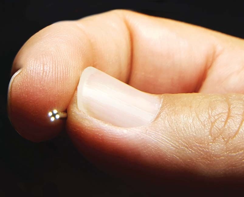 |
| Example chip-on-the-tip small-scale camera (Copyright 2020 Toshiba Imaging). |
Embedding of a camera does also involve adding a sufficient light source, either fibre optic lights or small-scale LEDs, as continuum robots are usually foreseen in applications requiring deployment in cluttered environments or within a human body in medicine such that ambient light is insufficient.
Using embedded image-based sensing is a common way to obtain information of the robot’s surrounding and relatively cost-efficient. Sampling rates for typical cameras range between 30-60Hz. The expense usually lies in the image-processing if more than pure image information is required, which also reduces the sampling rate eventually. Estimating the state of the robot or its environment from images is its own area of research and goes beyond the scope of this post.
Fibre-optic Sensing
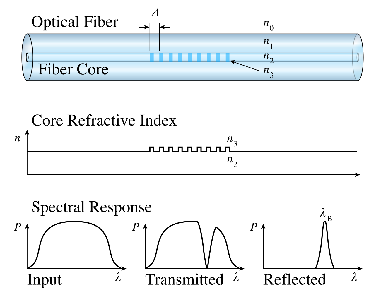
A promising sensing technology is optical fibres with inscribed fibre Bragg gratings (FBG). Each grating can be seen as an optical strain gauge. By inscribing several FBGs into one single optical fibre, it is possible to measure strain at various locations along its centreline. Arranging several fibres in a known geometrical configuration creates a sensor array with a high spatial sensor density and small physical dimensions. The sensor array can either consist of several distinct optical fibres or of a single multicore fibre with several fibre cores, each containing various FBGs. Often, the fibres are arranged in parallel to the centreline of the sensor array, which is referred to as a longitudinal arrangement. With the help of the known geometrical relations of the array’s cross-section, the shape of the deformed array can be reconstructed.
FBGs are special sections inscribed in optical fibres. Each grating is characterized by a specific Bragg wavelength. It reflects incoming light with exactly this wavelength (see Figure below). If the fibre is subject to longitudinal stress and/or temperature change, the reflected light spectrum shifts. Assuming that the sensor array is used under stable temperature conditions, the strain can be related to the observed wavelength shift. This locally observed strain information can then be used to determine point-wise curvature information. The curvature along the whole length of the fibre can then be determined by interpolation and the shape, respectively the curve, can be determined by integrating twice.
Using this underlying principle, a fibre-optic sensing system is composed of an optical interrogator, also known as measurement unit or data acquisition system, which is an optoelectronic instrument allowing the reading of multiple FBG sensors. During data acquisition, the interrogator measures the wavelength associated with the light reflected by the optical sensors and then converts it into engineering units. The sampling rate is usually about 1kHz. Post-processing is required to infer shape information from the wavelengths measurements.
Fiber-optic sensing systems have the advantage that fibres are small diameter (few hundred microns) and can easily be integrated into continuum robots. It allows for real-time acquisition of shape information in dynamic settings. While the fibres are available at affordable costs, the overall sensing system is quite expensive due to the optical interrogator which is highly specialized equipment. The accuracy of the fibre-optic sensing is dependent on the post-processing and calibration. Placement of the fibre within the robot has to be accurate in order to rely on geometric relationships in shape reconstruction. Determining shapes that originate from bending and twisting of the fibres can be challenging as this requires special fibre arrangements.
Electromagnetic Sensing
Electromagnetic (EM) spatial measurement systems determine the location of objects that are embedded with sensor coils. When the object is placed inside controlled, varying magnetic fields, voltages are induced in the sensor coils. These induced voltages are used by the measurement system to calculate the position and orientation of the object. As the magnetic fields are of a low field strength and can safely pass through human tissue, location measurement of an object is possible without the line-of-sight constraints of an optical spatial measurement system. Therefore, electromagnetic sensing is a great option for continuum robots in medical applications.
An electromagnetic tracking system is composed of a field generator which emits a low-intensity, varying electromagnetic field and establishes the position of the tracking volume, and sensors. Small currents are induced in the sensors by the varying electromagnetic field produced by the field generator. The characteristics of these electrical signals are dependent on the distance and angle between a sensor and the field generator. The sensors are small-scale and come in 6-DOF or 5-DOF versions. 6-DOF sensors report their position and orientation and are slightly larger (0.8 mm diameter x 9 mm length). 5-DOF sensors report their position and two of its orientation (pitch and yaw, except roll) which allows a smaller footprint (0.5mm diameter x 8mm length or 0.9 mm diameter x 6 mm length). The sensors are connected to a sensor interface unit which amplifies and digitizes the electrical signals and and minimizes the potential for data noise. The sensor interface unit connects to the system control unit, which calculates the position and orientation of each sensor and interfaces with the host computer. The measurement information, i.e., position and orientation, of the sensors is available at a measurement rate of 40Hz.
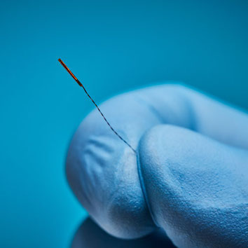 |
| Examlpe 5DOF electromagnetic tracking sensor with 0.45mm diameter, 6.3 mm length, and up to 4.1m lead wire (Copyright: 2022 Northern Digital Inc.) |
Electromagnetic tracking allows for real-time tracking of pose information with no line-of-sight restrictions and is relatively cost-efficient. In a state-of-the-art EM tracking systems (such as NDI Aurora v2, NDI Inc.), the stated root-mean-square-error (RMS) for 6-DOF sensors is 0.48 mm in position and 0.3° orientation and for 5-DOF sensors 0.7 mm in position and 0.2° in orientation in an environment free of electromagnetic disturbances. Any ferromagnetic material or insufficiently shielded cable may interfere with the field, lead to field distortions and as a result impact the system’s accuracy. Therefore, if electromagnetic sensing is used, the continuum robot and eventually parts of its actuation unit need to be build from non-ferromagnetic materials such as medical-grade stainless steel, aluminum, and titanium. Depending on the size of the continuum robot, embedding electromagnetic sensors into its body can be challenging. As can be seen on the picture, the sensors come with a straight, stiff part which can impact the continuum robot’s ability to bend continuously. While multiple sensors can be tracked at the same time, the number is limited to up to 8 and the sensors cannot be too close to one another to allow for proper tracking.
We will look at external sensors for continuum robots in next week’s 101 Sensing Part 2 blog post!