
Tendon-driven Continuum Robots
Continuous motion is most commonly achieved by using tendons in continuum robotics. In so called tendon-driven continuum robots (TDCR) several tendons are routed alongside the robot’s flexible backbone and fixed at different locations. TDCR can consist of multiple stacked segments, where each segment end is defined by the termination of one or multiple tendons. When pulling these tendons, a load will be applied to the compliant backbone and the corresponding segment will bend in the direction of the routed tendon. Tendon actuation is an extrinsic actuation principle, as no actuators are located within the robot’s structure.
Structure of TDCR
There exist two design principles in TDCR, which differ by the tendon path.
 The first design consists of a primary flexible, slender backbone. A finite number of spacer disks is equally distributed along the whole length of the TDCR. Guiding holes within the spacer disks are used to route the tendons along the robot backbone. This design realizes a partially constrained tendon path, in which the tendon path is straight within a subsegment (i.e. between two individual spacer disks), forming a series of line segments along the robot.
 The second design uses a backbone which usually has a larger diameter and features inner lumens to guide the tendons without the need of separate spacer disks. In contrast to the previous design, here a fully constrained tendon path is realized. It is assumed that the tendons follow a continuous curve, parallel to the backbone.
For both designs, several components have been considered for realizing the flexible backbone: Either as a single piece flexible tube or rod that has a uniform stiffness, a flexible tube, or rod with a cutting pattern to allow for non uniform stiffness, or a discrete assembly of multiple stacked compliant joints. Special care needs to be taken when choosing the material of the tendons and the guiding channels to minimize friction and possible stretching of the tendons. Commonly used tendons are either threads, wires, twisted or braided ropes, or tubes made of Nylon, Teflon, Kevlar, or NiTi.
Motion Capabilities
For each segment, any number of tendons can be employed and routed along the robot’s backbone, while at least two are needed to allow for bending in one degree of freedom (planar bending). Since tendons cannot be pushed, using one tendon results in a bending degree of freedom which can only be controller actively in one direction. A pair of antagonistic tendons, i.e., located on opposite sides of the backbone, is required for control of both directions for in-plane bending. Similarly, a minimum of three tendons is required for bending in two degrees of freedom (spatial bending). Spatial bending can also be realized with a total of four tendons, i.e., two antagonistic pairs as depicted below. It is important to note, that not all tendons can be independently actuated.
The tendon routing path determines the motion capabilities. Tendons can be employed using many different routing paths along the backbone, e.g. helical or converging paths. Tendonds can be co-located, i.e., tendons share the same routing channel but terminate at different segments. Alternatively, tendons can be routed through channels dedicated to the segment they are actuating.
 |
| General structure of a tendon-driven continuum robot. Tendons terminate at the end disk of each segment to actuate it. They are routed in parallel to the central backbone. For spatial bending either 3 tendons or 2 antagonistic pairs are used. This example TDCR has two segments actuated by antagonistic tendon pairs. |
Remarks
The design for a TDCR is a straightforward one to achieve continuous bending along the backbone. The use of tendons allows the transmission of forces from remotely located actuators to the backbone. This extrinsic actuation and the compactness of tendons allows miniaturization due to reduced weight and volume of the robot body. However, any increase of the number of segments requires an additional set of motors to actuate it, resulting in a bulky actuator system. This increase in complexity leads to limitations in performance as the number of segments cannot be increased indefinitely.
In addition, the use of tendons brings further complexities to the system. There is friction between the disks and the tendons that results in loss of transmission forces. The direction of frictional force is dependent on the direction of their bending. Depending on the material, the tendon itself may undergo elastic deformations that can result in their extension. Another property of tendons is that they can only support tension and tend to get slack in the presence of compression. When additional forces are applied, a portion of these forces are used to recover from the state of slack. This recovery leads to what is known as actuator backlash where the tendon does not behave as per the input from the actuators. Therefore, all of these complexities must be accounted for while developing a TDCR system.
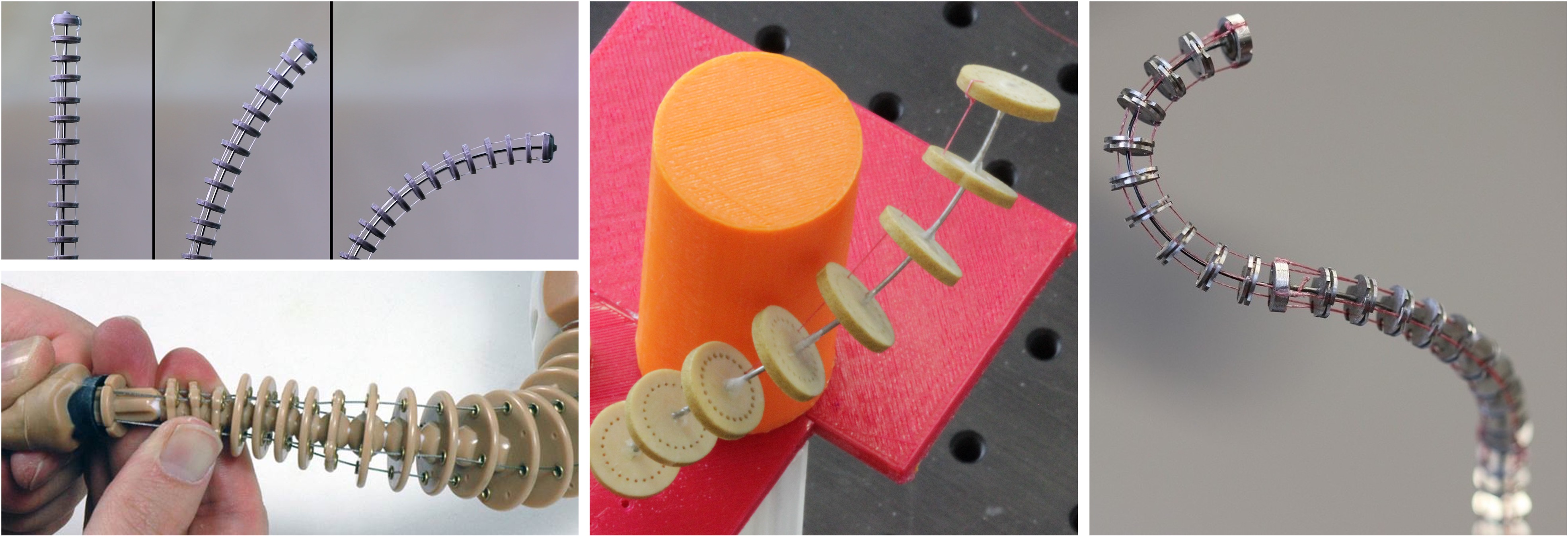 |
| Top left: From its initial straight configuration a single-segment TDCR is actuated by pulling on a single tendon causing planar bending. Bottom left: A TDCR with converging tendon paths actuated by antagonistic tendon pairs. Middle: A single segment TDCR with helical tendon path causing the robot to undergo bending and torsion as the tendon gets pulled. Right: Spatial bending of a three segment continuum robot. Three tendons are co-located. |
Further Reading: Curious to learn more about tendon-driven continuum robots? You don’t want to wait for the next blog post? Then this open access paper1 from my lab is for you!
References
-
P. Rao, Q. Peyron, S. Lilge, and J. Burgner-Kahrs: How to Model Tendon-Driven Continuum Robots and Benchmark Modelling Performance. Frontiers in Robotics & AI, 7:1-20, 2021, doi: 10.3389/frobt.2020.630245. ↩