University of Toronto, CANADA


        GRL Ontology

GRL (Goal-oriented Requirement Language) is a language for supporting goal-oriented modelling and reasoning of requirements, especially for dealing with non-functional requirements (NFRs). It provides constructs for expressing various types of concepts that appear during the requirement process. There are three main categories of concepts: intentional elements, intentional relationships, and actors. The intentional elements in GRL are goaltask, softgoal, belief and resource. The intentional relationships include: means-ends, decomposition, contribution, correlation, and dependency. They are intentional because they are used for models that allow answering questions such as why particular behaviours, informational and structural aspects were chosen to be included in the system requirement, what alternatives were considered, what criteria were used to deliberate among alternative options, and what the reasons were for choosing one alternative over the other.

This kind of modelling is different from the detailed specification of what is to be done. Here the modeller is primarily concerned with exposing "why" certain choices for behaviour and/or structure were made or constraints introduced. The modeller is not yet interested in the "operational" details of processes or system requirements (or component interactions). Omitting these kind of details during early phases of analysis (and design) allows taking a higher-level (sometimes called a strategic stance) towards modelling the current or the future software system and its embedding environment. Modelling and answering "why" questions leads us to consider the opportunities stakeholders seek out and/or vulnerabilities they try to avoid within their environment by utilising capabilities of the software system and/or other stakeholders, by trying to rely upon and/or assign capabilities and by introducing constraint how those capabilities ought to be performed.

GRL provides support for reasoning about scenarios by establishing correspondences between intentional GRL elements and non-intentional elements in scenario models. Modelling both goals and scenarios is complementary and may aid in identifying further goals and additional scenarios (and scenario steps) important to stakeholders, thus contributing to the completeness and accuracy of requirements.

1 GRL Ontology

1.1 Non-Intentional Element

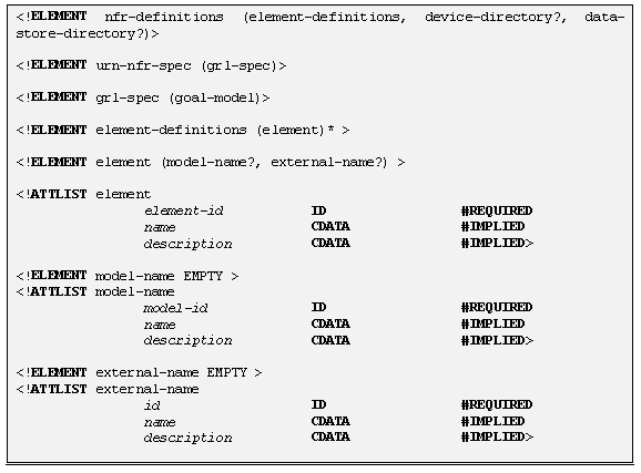
The language provides syntax for defining non-intentional elements. A non-intentional element may be imported from an external model. The main concern of these clauses is not to capture the syntax and semantics of the external model but to serves as references to the external model only. Non-intentional elements definition is used to navigate through the non-intentional model. The following statement defines a non-intentional element.
ELEMENT <Element name> [<Informal Textual Description>] [IS <External Name> FROM <Model Name>]

1.1.1 Textual notation

<GRL Specification> : :=     [<Non-Intentional Element Definitions>]
 <Goal Model Definition>
<Non-Intentional Element Definitions>::=  < Element Definition> { < Element Definition> }
<Element Definition> : :=    ELEMENT <Element Name>
 [<Informal Textual Description>]
 [IS <External Name> FROM <Model Name>]

1.1.2 XML definition

2 Goal model construction

A Goal-Oriented Requirement Model named <Model Name> can either be composed of a global goal model, or a series of goal models distributed in several actors.
If the model includes more than one actors, then there might exist <Dependency Series>, which represent the intentional dependency relationships between agents.

2.1.1 Textual notation

<GRL Model Definition>::=  GRL-MODEL <Model Name>
        <Model Constructors>
   END-GRL-MODEL.
<Model Constructors>::=   <Model Constructor> { <Model Constructor>}
<Model Constructor>::=    [<Actors>]
  <Intentional Elements>
  <Intentional Relationships>

2.1.2 XML definition

The following sections will introduce each of these kinds of constructs in turn.

Intentional elements

3.1 Overview

3.1.1 Textual notation

< Intentional Elements>::= < Intentional element > { < Intentional element >}
< Intentional element> ::=  <Task> | <Goal> | <Resource> | <Softgoal> | <Belief>

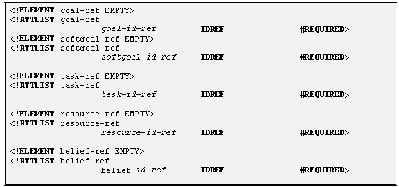
3.1.2 XML definition

3.2 Goal

A goal is a condition or state of affairs in the world that the stakeholders would like to achieve. How the goal is to be achieved is not specified, allowing alternatives to be considered.
A goal can be either a business goal or a system goal. A business goal express goals regarding the business or state of the business affairs the individual or organisation wishes to achieve. System goal expresses goals the target system should achieve, which, generally, describe the functional requirements of the target information system.

3.2.1 Textual notation

<Goal> ::= GOAL<Goal Name> [<Informal Textual Description>] [ ATTRIBUTE <Attributes>]
   [OWNER <Actor Name>]
<Attributes > ::= <Attribute > { <Attribute >}
<Attribute> ::= <Element Name>

3.2.2 Graphical notation

<Goal> ::= <Goal Symbol>
                       CONTAINS  <Goal Name > [Attributes]
<Goal Symbol> ::=
   
**In the Graphical notation, the following keywords are used to denote specific graphical meanings:
a) CONTAINS: indicates that its right-hand argument should be placed within its left-hand argument.
b) IS CONNECTED TO… BY: means that its right-hand argument is connected to its left-hand argument by the kind of link type referred to by the argument after keyword “BY”.
c) IS ASSOCIATED WITH indicates that its right-hand argument should be positioned next to its left-hand argument.

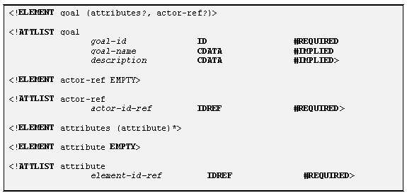
3.2.3 XML definition

3.2.4 Example

A goal is shown as rounded rectangle. For example, “Voice Connection Be Setup” is one basic goal to be achieved with any telecommunication system. How voice connection is to be set up (such as how reliable, over what medium) – may be done differently by each telecommunication provider.
In textual description, this goal would be defined with following statement:
 GOAL VoiceConnectionBeSetup

3.3 Task

A task specifies a particular way of doing something. When a task is specified as a sub-component of a (higher-level) task, this restricts the higher-level task to that particular course of action.
Tasks can also be seen as the solutions in the target system, which will satisfice the softgoals (called operationalizations in NFR). These solutions provide operations, processes, data representations, structuring, constraints and agents in the target system to meet the needs stated in the goals and softgoals.

3.3.1 Textual notation

<Task> ::=  TASK<Task Name> [<Informal Textual Description>] [<Attributes>]
   [OWNER <Actor Name>]

3.3.2 Graphical notation

< Task > ::= < Task Symbol>
    CONTAINS  < Task Name > [Attributes]
< Task Symbol> ::=

3.3.3 XML definition

3.3.4 Example

A task is shown as a hexagon. Make Voice-over-LAN is one particular way of setting up a voice connection.
In textual description, this task would be defined with following statement:
 TASK MakeVoiceConnectionOverLAN

3.4 Resource

A resource is an (physical or informational) entity, with which the main concern is whether it is available.

3.4.1 Textual notation

<Resource> ::= RESOURCE <Resource Name> [<Informal Textual Description>] [<Attributes>]
   [OWNER <Actor Name>]

3.4.2 Graphical notation

<Resource> : :=< Resource Symbol>
    CONTAINS  < Resource Name > [Attributes]
<Resource Symbol>::=
                      

3.4.3 XML definition

3.4.4 Example

Resources are shown as rectangles. In the voice-on-the-LAN architecture, bandwidth is a resource that must be available.
In textual description, this resource would be defined with following statement:
 RESOURCE LANBandwidth

3.5 Softgoal

A softgoal is a condition or state of affairs in the world that the actor would like to achieve, but unlike in the concept of (hard) goal, there are no clear-cut criteria for whether the condition is achieved, and it is up to subjective judgement and interpretation of the developer to judge whether a particular state of affairs in fact achieves sufficiently the stated softgoal.

3.5.1 Textual notation

<Softgoal> ::= SOFTGOAL [<Softgoal Name> IS]
   <Softgoal Type Name> OF <Softgoal Topic>
   [<Informal Textual Description>] [<Attributes>]
   [OWNER <Actor Name>]
<Softgoal Topic> ::= <Element Name>
3.5.2 Graphical notation
<Softgoal>::=< Softgoal Symbol>
    CONTAINS  <Softgoal Name> OF <Softgoal Topic> [Attributes]
<Softgoal Symbol> ::=


3.5.3 XML definition

3.5.4 Example

A softgoal, which is “soft” in nature, is shown as an irregular curvilinear shape. For instance, reliability of router is a softgoal to be achieved during the design of a telecom system.
In textual description, this softgoal would be defined with following statement:
 SOFTGOAL ReliabilityOFRouter

3.6 Belief

Beliefs are used to represent design rationale. Beliefs make it possible for domain characteristics to be considered and properly reflected into the decision making process, hence facilitating later review, justification and change of the system, as well as enhancing traceability.

3.6.1 Textual notation

<Belief> ::= BELIEF <Belief Name> [<Informal Textual Description>] [<Attributes>]
               [OWNER <Actor Name>]

3.6.2 Graphical notation

<Belief>::=< Belief Symbol>
                CONTAINS  < Belief Name> [Attributes]
<Belief Symbol> ::=
 

3.6.3 XML definition

3.6.4 Example

A belief is shown as an ellipse. In the following is an argument supporting that the task of VoiceLAN is lowering costs.

Intentional Relationships

Each model structure is a link connecting two elements. These structures together constitute the overal goal model. So they are seen as the basic building blocks of models.

4.1.1 Textual description

<Intentional Relationships>::= < Intentional relationship > { < Intentional relationship>}0 n
< Intentional relationship>::=  <Decomposition> | <Means-ends >
     | <Contribution > | <Correlation >
     | <Dependency>

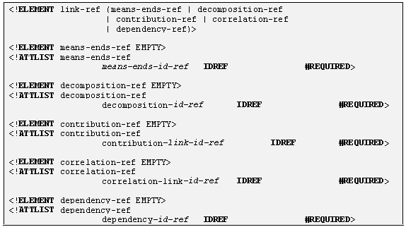
4.1.2 XML definition

4.2 Means-ends Relationship

GRL uses the MEANS-END statement to describe how goals are in fact achieved. Each task provided is an alternative means for achieving the goal. Normally, each task would have different types of impacts on softgoals, which would serve as criteria for evaluating and choosing among each task alternative.
MEANS-END < Means-Ends Identifier > FROM<Means element name> TO <Ends element name>
Graphically, a means-ends link connects an end node with the means node achieving it. In GRL, only goals are originally applicable to means-ends link. See Figure1 as an example. However, for convenience, in short hand forms for a combined structure, tasks and resources could also be connected by means-ends links.
A Task Means_Ends Structure connects a task with the means (tasks) to achieve it directly, which is a short hand form of one Task Decomposition Structure and the related Goal Means_Ends Structure. See Figure2 as an example.
A Resource Means_Ends Structure connects a resource with the means (tasks) to make it available, which is a short hand form of one <softgoal Contribution Structure>.See Figure 3 as an example.

4.2.1 Textual notation

<Means-Ends> ::= MEANS-ENDS [<Means-Ends Identifier>]
     FROM <Means Element > TO  <End Element >
<End Element> ::= <Goal Reference> | <Task Reference> | <Resource Reference>
<Resource Reference> ::=   RESOURCE <Resource Name>
<Means Element> ::= <Task Reference>
<Task Reference> ::= TASK <Task Name>
<Goal Reference>::= GOAL <Goal Name>
<Resource Reference> ::=   RESOURCE <Resource Name>

4.2.2 Graphical notation

<Means-Ends> ::=
  <End Element>
   {IS CONNECTED TO]<Means Element>
    BY < Means-Ends Link >}
<Means-Ends Link > : :=

4.2.3 Example

 Figure 1. Goal means-ends structure
 Figure 2. Task means-ends structure
     Figure 3. Resource means-ends structure

4.3 Decomposition Relationship

GRL DECOMPOSITON statement provides the ability to define what other elements need to be achieved or available in order for a task to perform.
DECOMPOSITION <Decomposition Identifier>  FROM <sub-element > TO < Decomposed Element >
Graphically, a decomposition link connects a node with its sub-components. In GRL, only tasks are originally decomposable, but for convenience, in short hand forms for a combined structure goals could also be connected by decomposition links. The sub-components of a task can be goal, task, resource, and softgoal.
A Task Decomposition Structure shows the essential components of a task, which include subtasks that must be performed, subgoals that must be achieved, resources that must be accessible, and softgoals that must be satisfied. See Figure 4 as an example.
A Goal Decomposition Structure connects a goal with its sub-goals directly, which is a short hand form of one Goal Means_Ends Structure and the related Task Decomposition Structure. See Figure 5 as an example.

4.3.1 Textual notation

<Decomposition> ::=  DECOMPOSITION [<Decomposition Identifier> ]
      FROM < Sub-Element > TO <Decomposed Element >
<Decomposed Element> ::= <Task Reference> | <Goal Reference>
<Sub-Element> ::=  <Task Reference>
     | <Goal Reference>
     | <Resource Reference>
     | <Softgoal Reference>

4.3.2 Graphical notation

<Decomposition> : :=
  < Decomposed Element >
   {IS CONNECTED TO < Sub-Element >
   BY < Decomposition Link >}
<Decomposition Link> ::=

4.3.3 XML definition

4.3.4 Example

  
             Figure 4. Task decomposition structure
 Figure 5. Goal decomposition structure

4.4 Contribution Relationship

The CONTRIBUTION relationship statement describes how softgoals, task, believes, or links contribute to others. A contribution is an effect that is a primary desire during modelling.
CONTRIBUTION [<Contribution Identifier > IS]
   <Contributor> HAS <Contribution type> CONTRIBUTION-TO <Contributee>
Graphically, a contribution link describes how one intentional element contributes to the satisficing of another intentional element.
  •  AND : The relations between the contributing elements are “AND”. Each of the sub-components is positive and necessary.
  •  OR : The relations between the contributing elements are “OR”. Each of the sub-components is positive and sufficient.
  •  MAKE : The contribution of the contributing element is positive and sufficient.
  •  BREAK : The contribution of the contributing element is negative and sufficient.
  •  HELP : The contribution of the contributing element is positive but not sufficient.
  •  HURT : The contribution of the contributing element is negative but not sufficient.
  •  SOME+ : The contribution is positive, but the extent of the contribution is unknown.
  •  SOME- : The contribution is negative, but the extent of the contribution is unknown.
  •  EQUAL : There is equal contribution in both directions.
  •  UNKNOWN : There is some contribution, but the extent and the sense (positive or negative) of the contribution is unknown.
  • A Softgoal Contribution Structure shows the contributions of softgoals or tasks towards a softgoal. See Figure 6 as an example.
    An argumentation structure could attach a belief to any link or node of a model, which denotes the contribution of a belief node to the link or node it attached to, and give some argument for future review and justification. See Figure 7 as an example.

    4.4.1 Textual notation

    <Contribution> ::=  CONTRIBUTION [<Contribution Identifier> IS]
       <Contributors> HAS <Contribution type> CONTRIBUTION-TO <Contributee>
    <Contributors>::= <Contributor > {“,” <Contributor>}0 n
    <Contributee > ::= <Softgoal Reference> | <Link Reference> |<Belief Reference>
    <Contributor > ::= <Softgoal Reference> | <Task Reference>
          | <Link Reference> | <Belief Reference>
    
    
    <Softgoal Reference> ::=  SOFTGOAL <Softgoal Name>
    <Belief Reference>::= BELIEF <Belief Name>
    <Link Reference> ::= <Decomposition link Reference> | <Means-ends link Reference>
         | <Contribution link Reference> | <Correlation link Reference>
         | <Dependency link Reference>
    <Decomposition link Reference> ::= DECOMPOSITION-LINK< Decomposition Identifier >
    <Means-ends link Reference> ::= MEANS-ENDS-LINK <Means-Ends Identifier>
    <Contribution link Reference> ::= CONTRIBUTION-LINK <Contribution Identifier>
    <Correlation link Reference> ::= CORRELATION-LINK <Correlation Identifier>
    <Dependency link Reference> ::= DEPENDENCY-LINK <Dependency Identifier>
    < Contribution Type> ::= Break | Hurt | Some- | Unknown | Equal
          | Some+ | Help | Make | And | Or

    4.4.2 Graphical notation

    < Contribution> ::= <Contributee Element>
       {IS CONNECTED TO  <Contributor Element>
       BY < Contribution Link >}
    <Contribution Link> ::=

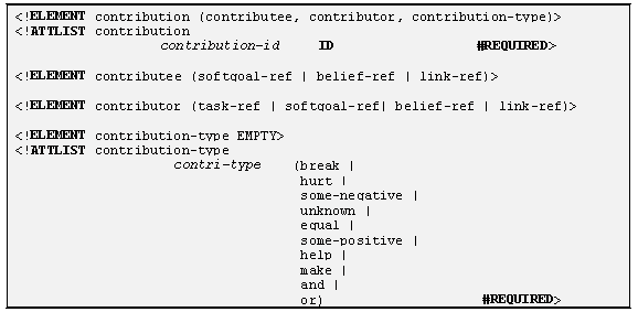
    4.4.3 XML definition

    4.4.4 Example

     Figure 6. Softgoal contribution structure
     Figure 7. Argumentation structure

    Actor

    An actor is an active entity that carries out actions to achieve goals by exercising its know-how. Graphically, an actor may optionally have a boundary, with intentional elements inside.

    Actor statement defines an actor and its attributes.

    ACTOR  <Actor Name> <Actor Description> [<Attributes>]

    5.1.1 Textual notation

    <Actors>::= <Actor > { <Actor>}
    <Actor>::=  ACTOR <Actor Name> [<Informal Textual Description>] [<Attributes>]

    5.1.2 Graphical notation

    <Actor> ::=<Actor Symbol>
      CONTAINS <Actor Name> [<Attributes>]
      [IS ASSOCIATED WITH
      <Actor Boundary Symbol>
      CONTAINS<Intentional Elements > <Intentional Links> ]
    <Actor Symbol> ::=
    <Actor Boundary Symbol>::=

    5.1.3 XML definition

    5.1.4 Example

    Actors are shown as a circle with the name of the actor inside in graphical representations. The boundary of an actor is shown as a grey shadow with the actor icon inside or nearby. For example, within a VoiceLAN environment, an actor “Call Server” on the LAN provides the call control functionality normally provided by a PBX. Figure 8 is an example of actor structure.
    In the component base, each intentional element has an attribute named as “Owner” by default:
    … …
    owner: <Actor Name>
    … …
     Figure 8. Actor with intentional elements and links

    Dependency

    The Dependency statement of GRL describes an intentional relationship between two actors, i.e., one actor (<Depender>) depends on another actor (<Dependee>) on something (<Dependum>).
    DEPENDENCY [<Dependency Identifier>] <Depender> DEPENDES-ON <Dependee> FOR <Dependum>

    6.1.1 Textual notation

    <Dependency> ::= DEPENDENCY [<Dependency Identifier> IS]
         <Depender> DEPENDES-ON <Dependee> FOR <Dependum>
    <Depender> ::=  DEPENDER <Actor Name> [“.”<Sub-Element>]
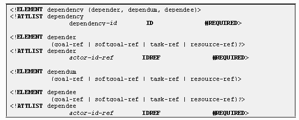
    <Dependee> ::= DEPENDEE <Actor Name> [“.” <Sub-Element >]
    <Dependum> ::= DEPENDUM <Sub-Element>

    6.1.2 Graphical notation

    <Dependency Link> ::=
      <Depender> IS CONNECTED TO <Dependum>
               IS CONNECTED TO  <Dependee>
                BY <Dependency Link>
    <Depender> ::=  <Actor > | <Intentional element>
    <Dependee> ::= <Actor > | <Intentional element>
    <Dependum> ::= <Intentional element>
    <Dependency Link> ::=  

    6.1.3 XML definition

    6.1.4 Example

    In Figure 9, a model composed of many actors, and with dependencies is shown. With this kind of model, the intentional relationships between actors can be better captured and analyzed. There are altogether four types of dependencies, which permits different degree of freedom for the depended actor to make decision.
     Figure 9. A model composed of many actors and their dependencies

    Correlations

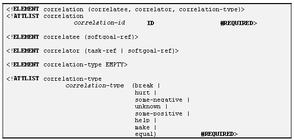
    Correlations allow for expressing knowledge about interactions between intentional elements in different categories, and to encode such knowledge. A correlation link is the same as a contribution link except that the contribution is not an explicit desire, but is a side-effect.This type of relationship is captured by a CORRELATION statement which is defined as follows:
    CORRELATION <Correlation Identifier> IS
      <Correlator > HAS <Correlation Type>  CONTRIBUTION-TO <Correlatee>
    The effect of all incoming correlation links on a softgoal may need to be evaluated by the user on a case by case basis.

    7.1.1 Textual notation

    <Correlation> ::= CORRELATION [<Correlation Identifier> IS]
      <Correlator > HAS <Correlation Type>  CONTRIBUTION-TO <Correlatee>
    <Correlatee> ::= <Softgoal Reference>
    <Correlator> ::= <Softgoal Reference> | <Task Reference>
    <Correlation Type> ::= Break | Hurt | Some- | Some+ | Help | Make | Equal

    7.1.2 Graphical notation

    <Correlation> ::= <Correlatee> IS CONNECTED TO  <Correlator>
      BY <Correlation Link>
    <Correlation Link> ::=
                             

    7.1.3 XML definition

    7.1.4 Example

    In Figure 10, a goal model is given, which is made up of softgoals and contribution relationships. A model can also be made up of several such goal model structures. Each of these structures is a category of requirement. They interact through <Correlation Structure Series>. See Figure 11 as an example.
     Figure 10. A Model composed of basic model structure
     Figure 11. Model structure series connected with correlations